0
-
An empty cart
You have no item in your shopping cart


Precision Injection Molded Automotive Components for Improved Performance
Injection molded automotive components are parts created by forcing molten plastic into a steel mold, which then cools into a precise, durable shape. This process allows for complex geometries and tight tolerances that are essential for everything from dashboard panels to under-hood housings. The key benefit is that it produces high-strength, lightweight parts at a rapid pace, helping vehicles become more fuel-efficient without sacrificing quality. You simply design the mold, select the right polymer, and the machine does the rest, delivering consistent results every cycle.

Precision molding in modern vehicle production dictates the tight tolerances for everything from a dashboard panel to a complex engine sensor housing. It ensures each injection molded automotive component fits perfectly the first time, eliminating the need for wasteful adjustments during assembly. This level of accuracy comes from carefully controlled melt temperatures and highly regulated cavity pressures during the cycle. A slight variation in mold cooling channels can mean the difference between a flawless bumper clip and one that rattles after a thousand miles. For critical parts like intake manifolds, this method guarantees consistent wall thickness and durable structural integrity, directly affecting how the car performs long-term. Advanced simulation software now predicts and corrects warpage before steel even touches the press, saving both time and material waste.
High-pressure tooling forges under-the-hood parts by forcing molten polymer into precision-machined cavities at extreme velocities, enhancing molecular alignment for superior strength. This pressure compacts the material against cold mold surfaces, minimizing warpage in components like air intake manifolds or oil pans. The process enables consistent dimensional stability under thermal stress, achieved through a specific sequence:
Each step locks in the tight tolerances needed for sealing and vibration resistance directly under the hood.
Advances in thermoplastics enable dashboards and interior trim to integrate multiple functions through single-shot molding. Low-odor polypropylene compounds now replace painted parts for grained, color-consistent surfaces, reducing volatile emissions. Melt-flow optimization allows complex geometries like integrated air vents or wiring channels without secondary assembly. Olefin-based elastomers provide tactile soft-touch zones with scratch resistance, while glass-reinforced variants maintain dimensional stability under temperature cycling.
For injection molded automotive components, material selection for load-bearing parts prioritizes high mechanical strength, stiffness, and impact resistance, typically using reinforced thermoplastics like glass-filled nylon or polypropylene. Fiber reinforcement dictates load capacity, with short-glass fibers improving tensile modulus but reducing elongation. In contrast, aesthetic parts focus on surface finish, color stability, and UV resistance, employing materials like ABS or ASA. A critical trade-off arises when a single component must serve dual roles.
Combining structural ribs or steel inserts in aesthetic resins can meet load demands without sacrificing appearance, though weld-line strength and flow behavior must be validated via simulation.
The practical selection balances filler content, thermal expansion differences, and cosmetic defect risk (e.g., sink marks) against the targeted mechanical performance under hood or interior conditions.
Polyamide and glass-filled resins are selected for structural automotive components due to their enhanced mechanical properties. The addition of glass fibers significantly increases tensile strength and stiffness, making these materials suitable for load-bearing parts like engine mounts and transmission brackets. Their creep resistance under sustained stress ensures dimensional stability in high-temperature environments. Glass-filled polyamide excels in replacing metal where weight reduction is critical, while maintaining impact resistance for crash-related structures. Warpage must be controlled through optimized mold design and fiber orientation. A common choice is PA6-GF30 for balanced strength and processability.
Q: How do glass-filled resins improve polyamide’s performance in structural applications?
A: They elevate the material’s elastic modulus and heat deflection temperature, enabling it to withstand cyclic loads and under-hood thermal conditions without failure.
For load-bearing and aesthetic injection molded automotive components, elastomeric compounds for vibration dampening and seals offer decisive advantages. Their high elasticity and internal molecular friction efficiently absorb and dissipate vibrational energy, preventing resonance in adjacent rigid parts. Selecting a compound with the correct durometer (e.g., 60–80 Shore A for engine mounts) ensures effective isolation. For sealing applications, compression set resistance is critical; a
This targeted material choice directly enhances noise reduction and joint integrity without compromising the part’s aesthetic finish.
For complex automotive geometries like multi-vane air ducts or intricate connector housings, tooling design strategies must prioritize strategic actions over static features. Conformal cooling channels are critical, as they follow the part’s contours to eliminate hot spots and drastically reduce cycle times. For undercuts, collapsible cores and hydraulic lifters allow the mold to release detailed threads or snap-fits without part damage. Multi-action slide systems are deployed to handle deep ribbing or compound-angle bosses, while CAD-integrated mold flow analysis predicts weld line placement, ensuring structural integrity in load-bearing brackets. A key detail is designing for modular inserts; this allows quick swap-out of worn or damaged sections for complex textures or shut-offs, directly extending tool life and lowering per-unit cost for high-volume production.
For high-volume automotive components like connectors or interior clips, multi-cavity molds paired with hot runner systems dramatically boost efficiency without sacrificing precision. Each cavity produces an identical part per cycle, while the hot runner keeps the plastic molten within the manifold, eliminating runner waste and reducing cycle times. This design demands balanced flow simulation to ensure each cavity fills uniformly—critical for maintaining tight tolerances across complex geometries. Properly sized gate locations and thermal profiling prevent sink marks or warpage, ensuring every component meets strict structural specs.
Why are hot runners preferred over cold runners for multi-cavity automotive molds? Hot runners eliminate solidified runner scrap, reduce material costs, and enable faster cycle times, which is essential for the high repeatability required in automotive production.
For hollow automotive sections like intake ducts or handle cores, gas-assist and water-assist molding are game-changers. Gas injection pushes nitrogen through the melt to form internal cavities, slashing material use and warpage. Water-assist uses a liquid core to create smoother, thinner walls with faster cycle times—ideal for complex, lightweight structural parts. Hollow section tooling design must integrate precise gas or water injection points to avoid short shots or wall thickness variation.
Advanced forming techniques directly reduce mass in injection molded automotive components by allowing thinner wall sections without sacrificing structural rigidity. Gas-assisted injection molding creates hollow channels within the part, eliminating thick resin areas that contribute unnecessary weight. Similarly, foam injection molding introduces a uniform cellular core, significantly lowering density while maintaining impact resistance. These methods also minimize sink marks and warpage, enabling designers to draft lighter geometries that would otherwise require heavy reinforcing ribs. By optimizing material distribution, you achieve a component that is both lighter and functionally superior, lowering the vehicle’s overall mass and improving fuel efficiency without compromising durability.
Thin-wall molding optimizes fuel-efficient vehicle platforms by reducing component wall thickness to sub-millimeter levels while maintaining structural integrity. This technique employs high-flow engineering resins and precise tooling to achieve consistent cavity fill at elevated injection speeds. The process directly lowers part weight without sacrificing impact resistance or thermal stability, critical for underhood and interior applications. Flow length-to-wall thickness ratios exceeding 200:1 are achievable through advanced mold design and process control.
Foaming and core-back processes directly reduce panel weight in injection molded automotive components by introducing gas into the polymer melt. In foaming, a chemical or physical blowing agent creates a cellular core surrounded by a solid skin, lowering density without sacrificing surface quality. The core-back technique sequences mold opening after initial injection, allowing the melt to expand into a thicker cavity, producing a foamed core. For implementation, follow:
These methods achieve 10–30% weight savings while maintaining structural integrity for interior and underhood panels.
For injection molded automotive visible trim, surface finish and gloss control are critical because the human eye instantly spots imperfections in a door panel or dashboard. You achieve the right look by precisely managing mold temperature, melt flow, and tool texture—a high-gloss finish demands a polished, mirror-like steel mold, while a low-gloss, matte surface typically needs a specific EDM texture or vapor-blasted tool surface. Getting the gloss just right often involves adjusting injection speed and holding pressure to prevent sink marks or flow lines. The key detail to watch is gate placement, as improper gating can create swirl patterns or gloss variations on the show surface. Mold steel quality and regular polishing also prevent haze or dull spots from developing over production runs.
Textured molds and in-mold decoration (IMD) methods let you skip post-mold painting while giving auto trim a high-end feel. A textured mold surface, often made via chemical or laser etching, creates a soft-touch or grainy finish right on the part, hiding fingerprints and minor scratches on dashboards or door panels. For IMD, a pre-printed film is placed inside the cavity; during injection, the plastic bonds to it, adding wood, carbon, or metallic looks directly. Both reduce secondary steps and improve durability—textured surfaces resist wear, while IMD’s graphics won’t peel like stickers.
| Aspect | Textured Molds | In-Mold Decoration |
|---|---|---|
| Finish feel | Tactile grain or soft-touch | Smooth graphic layer |
| Design change | Requires new mold etching | Swap film only |
| Wear resistance | Excellent (inherent to material) | Good (bonded film) |
For visible trim in injection molded automotive components, Color-Pigmented Resins vs. Post-Mold Painting presents a direct trade-off in surface finish and gloss control. Color-pigmented resins achieve uniform, scratch-resistant color-through finishes, eliminating paint chipping on high-wear areas like door handles. Post-mold painting, however, offers superior gloss and metallic effects for premium trims, but adds cycle time and potential adhesion defects. The choice hinges on durability versus aesthetic flexibility.
Which method provides better UV resistance for exterior trim? Color-pigmented resins typically resist UV fading longer than painted surfaces, as the pigment is integrated throughout the material rather than relying on a thin coating layer.
For high-stress injection molded automotive components, quality metrics and testing must validate structural integrity under fatigue and impact. You should demand mechanical testing like tensile, flexural, and Izod impact tests on every production batch to ensure material strength. Dimensional metrology using CMM or optical scanning is non-negotiable, verifying critical tolerances against the CAD model to prevent stress risers. Incorporate validated process capability indices (Cpk ≥ 1.67) for all melt flow and pressure parameters. Final validation requires accelerated life-cycle testing, such as thermal cycling and vibration tests simulating under-hood conditions. Reject any component showing micro-cracks or delamination in cross-section analysis. These quality metrics and testing protocols directly minimize field failures, guaranteeing your components withstand continuous mechanical and thermal loads.
Dimensional stability under thermal cycling directly determines whether an injection molded component retains its critical fit and function through repeated engine bay or undercarriage temperature swings. Controlled CTE matching between the polymer and any filler system is non-negotiable. Validation follows a clear sequence:
Even a 0.1% linear shift at a mounting boss can propagate into a leakage failure at a gasket interface. Selecting semi-crystalline polymers with nucleating agents and performing stress-relief annealing on ejected parts ensures repeatable, unshifting geometry over plastic injection molding automotive parts the vehicle’s lifetime.
Impact resistance validation for brackets and housings uses instrumented drop-tower or pendulum tests to simulate low-velocity collisions during assembly or service. Engineers correlate failure modes—brittle fracture, ductile tearing, or hinge cracking—with notch radius and gate location on the mold. Dynamic stress-strain curves from 5–15 m/s impacts determine absorbed energy thresholds, typically calibrated to a 5–10 J requirement for radiator mounts or ECU enclosures.
In the automotive plant, we’ve closed the loop on injection molded interior trim. Rejected door panels and bumper fascias are no longer waste; they are ground, re-compounded, and fed directly back into our presses as recycled post-industrial resin, maintaining tight dimensional specs for new glove-box housings.
A single washing process removes paint and contaminants, allowing us to reuse up to 30% regrind without altering mold flow or surface finish.
Our scrap conveyor now feeds the granulator instead of the landfill, turning yesterday’s molding flash into tomorrow’s dash bezel.
For injection molded automotive components, post-consumer resin streams for non-visible parts rely on carefully sorted, recycled plastics from household waste, such as polypropylene and polyethylene. These streams are specifically directed to under-hood components, interior brackets, and underbody shields where aesthetic surface finish is irrelevant. Processing requires rigorous contaminant removal to prevent defects, ensuring consistent melt flow and mechanical properties for structural performance. The material is typically compounded with virgin resin to stabilize viscosity, enabling reliable shot-to-shot molding without altering tooling or cycle times.
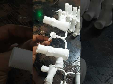
In injection molding for automotive components, closed-loop scrap reuse means immediately regrinding runners, rejected parts, and sprues right at the press. This material feeds directly back into the production cycle for the same or similar parts, cutting raw plastic waste dramatically. This zero-waste material flow reduces resin costs without sacrificing part quality, as long as regrind ratios stay consistent. You must carefully control regrind particle size and contamination to avoid weakening structural components like brackets or housings. Most facilities simply blend virgin pellets with regrind at a set percentage, running scrap through granulators beside each cell.

Closed-loop scrap reuse directly recaptures and reintegrates production waste into the same manufacturing process, slashing material costs and landfill burden without relying on external recycling.
The shift to electrification demands that injection molded components house sensitive sensors directly within high-voltage battery packs and power electronics. A mold’s gating design now must account for integrated connectors that seal out moisture while allowing signal transmission through the plastic. In one EV program, we optimized a PBT housing for an EMC shield by placing its gate to avoid shear-induced warpage near the sensor lens. How do you maintain dimensional stability for a sensor housing that also integrates a cooling channel? The answer lies in using a low-shrinkage liquid crystalline polymer and a multi-cavity mold with sequential valve gating, ensuring the sensor pocket holds ±0.05 mm while the channel remains leak-free. This synergy between thermal management and signal integrity defines modern automotive molding.
Overmolding for sealed battery enclosures fuses a rigid thermoplastic substrate with a resilient elastomeric seal in a single process, eliminating secondary gaskets. This creates a hermetic barrier around high-voltage cells. The sequence involves molding the structural core, then injecting a softer TPE or liquid silicone rubber directly over designated flange areas. Integrated sealing geometries route the elastomer into micro-channels, preventing electrolyte ingress and thermal expansion leaks. The process also allows embedding sensor housings within the overmolded layer, shielding wiring from vibration without compromising the enclosure’s IP67 rating.

Conductive polymer compounds for EMI shielding enable injection molding of sensor housings and electrification components that block electromagnetic interference without secondary metallization. These compounds incorporate conductive fillers like carbon fibers or stainless-steel flakes, achieving high shielding effectiveness while maintaining design flexibility for complex geometries. The material’s integrated EMI attenuation eliminates post-processing steps, reducing cycle times and assembly costs. Formulations must balance filler loading for conductivity against mechanical integrity, ensuring robust performance under thermal cycling in power electronics enclosures.
Conductive polymer compounds directly dissipate electromagnetic interference within injection-molded sensor housings and electrified components, integrating shielding into the part’s structure rather than applying it as a secondary layer.
In the plant, every second of the injection molding cycle for a dashboard carrier carries a direct cost. By reducing the cycle time from 45 to 38 seconds through optimized cooling channel design and a faster-acting ejection sequence, the molder shaves 15% off the per-part cost without altering the glass-filled nylon material. This efficiency gain allows the same press to produce an additional 700 components per shift, lowering the unit overhead for the automotive OEM’s just-in-time delivery schedule. The shortened cycle also reduces energy consumption per part, making the entire process more competitive against lower-wage alternatives while maintaining the tight dimensional tolerances required for snap-fit assembly.
For automotive components, conformal cooling channel layouts in mold bases minimize cycle time by precisely tracing complex part geometries, eliminating uneven cooling. Unlike straight drilled lines, these channels follow the contour of features like ribs or bosses, achieving uniform heat extraction. This reduces residual stress and warpage, directly enabling faster ejection. Optimized thermal management through conformal channels allows for reduced cooling phases, cutting per-part seconds from the cycle. Q: How do conformal layouts affect mold base durability? A: By eliminating hot spots, they reduce thermal fatigue and cracking, extending the mold base’s service life.
Automated part removal and trimming systems directly slash cycle times in automotive injection molding by eliminating manual intervention at the press. A robotic extractor grips the hot component within the mold-open window, immediately transferring it to a synchronized trimming station. This removes flash and gates while the press is already cycling for the next shot. The sequence is critical:
This closed-loop automation ensures consistent, high-speed part finishing without secondary operators, reducing per-part labor and cooling waste to maximize throughput.
The future of high-volume automotive plastics in injection molding pivots on multi-material hybridization to achieve radical weight reduction without sacrificing crash performance. Expect widespread adoption of self-reinforcing polypropylene compounds that flow into ultra-thin wall sections, slashing cycle times while maintaining stiffness.
In-mold assembly of dissimilar plastics—such as integrating a thermoplastic elastomer seal directly onto a structural nylon carrier—will eliminate secondary operations and reduce part counts.
Bio-attributed grades, derived from mass-balanced feedstock, will enable carbon-neutral interior components without retooling. Simultaneously, advanced thermal management in molds will allow precise crystallinity control in semi-crystalline resins, optimizing weld-line strength for visible structural parts like door modules. This shift demands molders master closed-loop process control for viscosity-sensitive, high-flow materials to consistently replicate micron-level surface textures for Class-A finishes.
Hybrid metal-plastic bonding for chassis components leverages injection molding to directly overmold a continuous fiber-reinforced thermoplastic onto a stamped metal insert, creating a single structural part. This process eliminates secondary fasteners and adhesive curing, achieving a material-efficient joint that is critical for lightweighting. The technique relies on the thermal shrinkage of the plastic around micro- or macro-mechanical interlocks on the metal surface, ensuring load transfer without creep. This integration allows a single hybrid component to replace multiple welded steel stampings, directly reducing assembly time and overall part count while maintaining torsional stiffness. For engineers, direct overmolding with structural adhesives applied in-line within the mold cycle remains the most reliable method for high-volume production, as it prevents galvanic corrosion and ensures consistent bondline thickness across varying flange geometries.
| Aspect | Hybrid Bonding Approach | Benefit for Chassis |
|---|---|---|
| Joint method | Overmolding + in-mold adhesive | No post-process welding |
| Weight reduction | 30–50% vs. all-steel assembly | Lower unsprung mass |
| Cycle time | 60–90 seconds per part | Compatible with high-volume lines |
| Corrosion | Sealed plastic interface | Eliminates bimetallic galvanic paths |
Self-healing polymers in interior touch points allow injection-molded surfaces like steering wheel grips and gear shifters to repair fine scratches from daily use. These materials use microcapsules that release a healing agent when damaged, restoring the finish without any user intervention. This technology works best on shallow surface abrasions rather than deep gouges, making it ideal for high-contact areas like console lids and armrests. The polymer restores its own gloss over hours, keeping the cabin looking fresh.
Q: How do self-healing polymers fix scratches in door handles? A: When a scratch occurs, embedded microcapsules break open, releasing a liquid that fills the crack and hardens to delete the mark.